Blog 3 – Turtlebot 3
2/8/26
Introduction
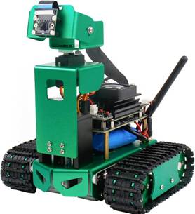
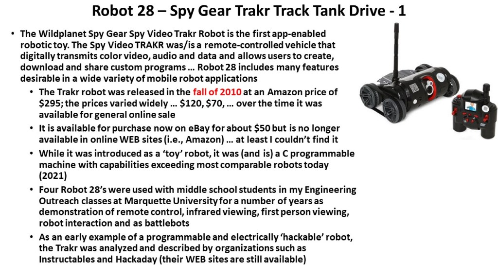
The TurtleBot series was created to democratize robotics—its core objective was to provide an affordable, standardized, ROS‑native mobile robot that anyone could learn from, modify, and use for research. Its significance lies in becoming the world’s most widely adopted open‑source robotics platform for education and prototyping, shaping how modern ROS developers learn and build.
Each version aligned with major ROS milestones:
- TurtleBot1 (2010–2011): First ROS‑ready consumer robot.
- TurtleBot2 (2012): More robust base (Kobuki).
- TurtleBot3 (2017): Modular, customizable, ROS1→ROS2 bridge.
- TurtleBot4 (2022+): Fully ROS2‑native, modern sensors, Create 3 base.
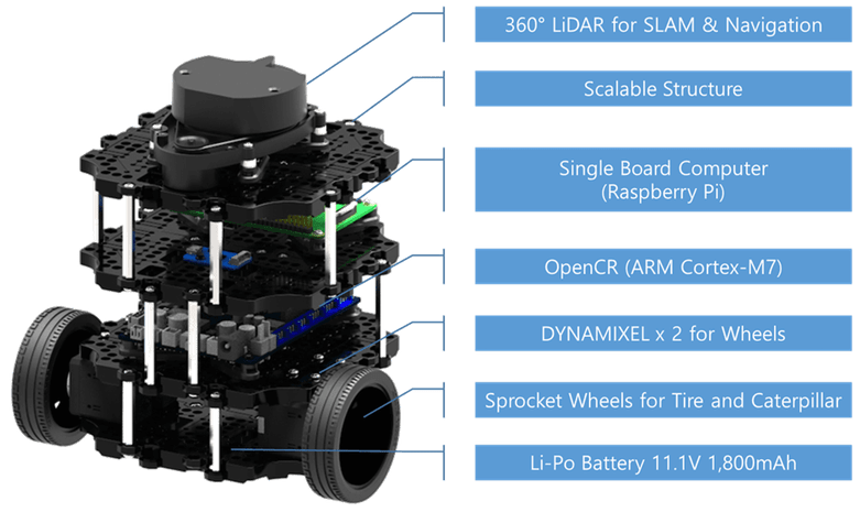
With built‑in LiDAR, depth cameras (Turtlebot 4), and ROS2 support, modern TurtleBots allow students and researchers to work on:
- SLAM
- Navigation (Nav2)
- Multi‑robot systems
- Perception and AI
- Human‑robot interaction
All without needing expensive industrial hardware.
TurtleBot line remains significant because it:
- Provides a reference architecture for ROS2‑native mobile robots.
- Demonstrates best practices in sensor integration, power design, and software stack organization.
- Offers a baseline platform for benchmarking navigation, SLAM, and perception algorithms.
- Continues to evolve with ROS2 Humble, Jazzy, and Gazebo Sim support
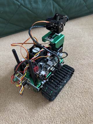
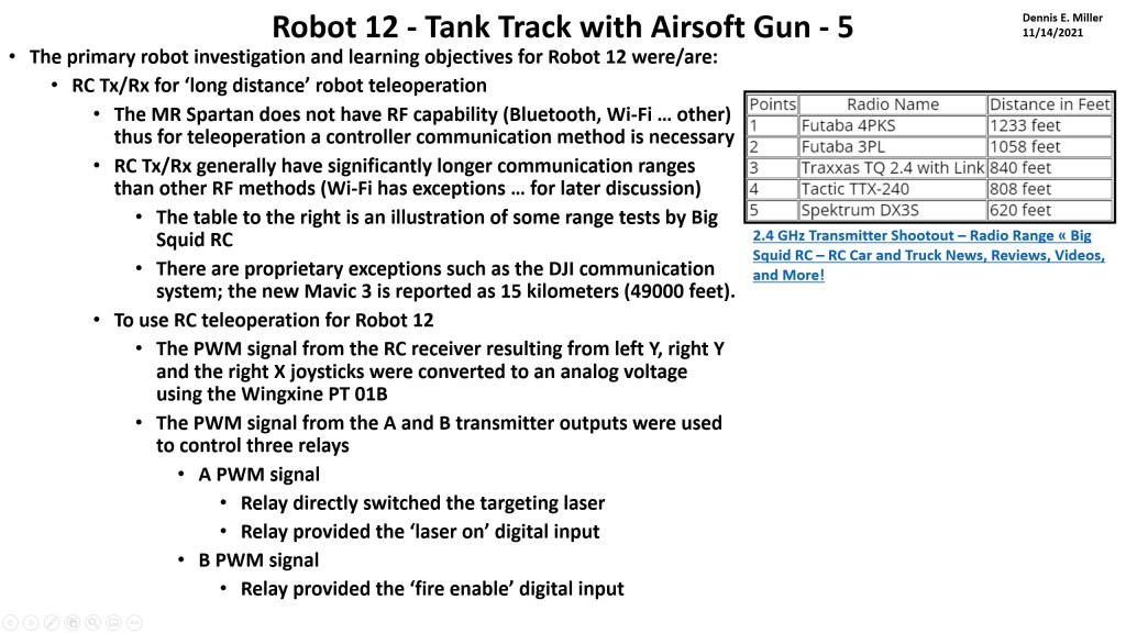
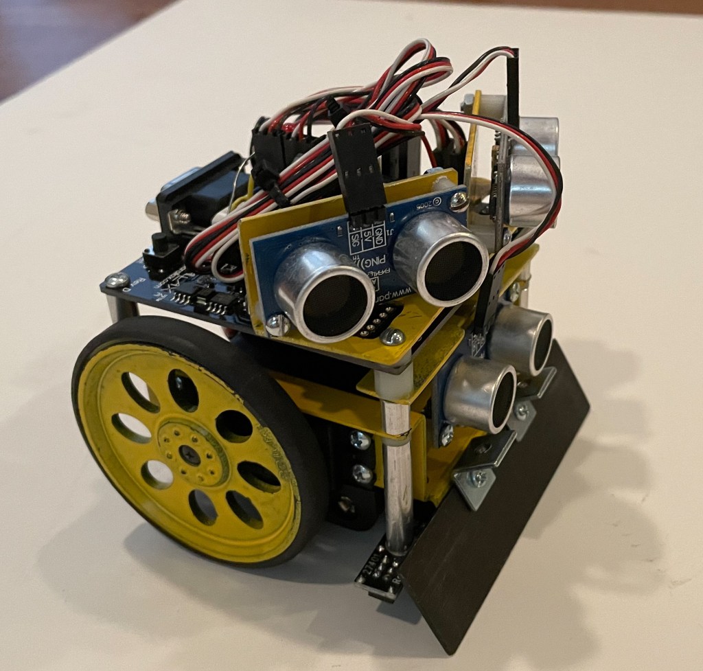
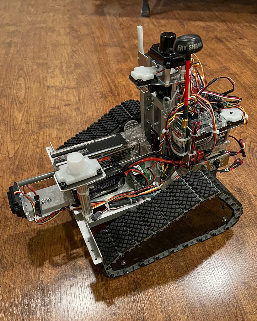
I purchased a Turtlebot 3 a few years ago for the reasons described above. After using it for a while it has sat on a shelf until recent work on robotics has again made it relevant. This blog describes the (rather long and tedious) process of updating the software and some testing of the available functions.
Setup Process
The following describes the process of setting up the Turtlebot 3. The document was generated by Sonnet 4.5 (Claude) as summary of the actions taken.
OpenCR 1.0 Board Specifications:
| Component | Specification |
| MCU | STM32F746ZGT6 (ARM Cortex-M7, 216MHz) |
| Flash | 1MB |
| SRAM | 320KB |
| IMU | MPU9250 (3-axis gyro, 3-axis accel, 3-axis mag) |
| Motor Ports | 4x Dynamixel TTL (3-pin) |
| Power | 7-14V input (battery), 5V/3A output |
| USB | Micro-B (programming/communication) |
| Buttons | 2x push buttons (SW1, SW2) |
| LEDs | 4x user LEDs |
| GPIO | Arduino-compatible headers |
TurtleBot3 Setup Documentation
Raspberry Pi 4 | Ubuntu 22.04 | ROS2 Humble
1. Overview
This document describes the complete setup process for TurtleBot3 on a Raspberry Pi 4 running Ubuntu 22.04 with ROS2 Humble. The setup includes system configuration, ROS2 installation, TurtleBot3 packages, and hardware configuration.
Final Working Configuration
| Component | Status | Notes |
| Ubuntu 22.04 | ✓ Working | On Raspberry Pi 4 |
| ROS2 Humble Desktop | ✓ Working | Full install with RViz2 |
| TurtleBot3 Packages | ✓ Working | Built from source |
| OpenCR Firmware | ✓ Updated | Flashed via x86 PC |
| LiDAR (LDS-01) | ✓ Working | /dev/ttyUSB0 |
| Motors | ✓ Working | Via OpenCR /dev/ttyACM0 |
| Keyboard Teleop | ✓ Working | Full motor control |
2. ROS2 Humble Installation
Step 2.1: Configure Locale
sudo apt update && sudo apt install -y locales
sudo locale-gen en_US en_US.UTF-8
sudo update-locale LC_ALL=en_US.UTF-8 LANG=en_US.UTF-8
export LANG=en_US.UTF-8
Step 2.2: Add ROS2 Repository
sudo apt install -y software-properties-common
sudo add-apt-repository -y universe
sudo apt update && sudo apt install -y curl gnupg lsb-release
sudo curl -sSL https://raw.githubusercontent.com/ros/rosdistro/master/ros.key -o /usr/share/keyrings/ros-archive-keyring.gpg
echo “deb [arch=$(dpkg –print-architecture) signed-by=/usr/share/keyrings/ros-archive-keyring.gpg] http://packages.ros.org/ros2/ubuntu $(source /etc/os-release && echo $UBUNTU_CODENAME) main” | sudo tee /etc/apt/sources.list.d/ros2.list > /dev/null
Step 2.3: Install ROS2 Humble
sudo apt update && sudo apt upgrade -y
sudo apt install -y ros-humble-desktop
sudo apt install -y ros-dev-tools python3-colcon-common-extensions python3-rosdep
Step 2.4: Initialize rosdep
sudo rosdep init
rosdep update
Step 2.5: Add ROS2 to bashrc
echo “source /opt/ros/humble/setup.bash” >> ~/.bashrc
3. TurtleBot3 Package Installation
Step 3.1: Install Dependencies from apt
sudo apt install -y ros-humble-cartographer ros-humble-cartographer-ros
sudo apt install -y ros-humble-navigation2 ros-humble-nav2-bringup
sudo apt install -y ros-humble-dynamixel-sdk ros-humble-turtlebot3-msgs ros-humble-turtlebot3
Step 3.2: Create Workspace and Clone Packages
Important: Always source ROS2 before building.
source /opt/ros/humble/setup.bash
mkdir -p ~/turtlebot3_ws/src
cd ~/turtlebot3_ws/src
git clone -b humble https://github.com/ROBOTIS-GIT/DynamixelSDK.git
git clone -b humble https://github.com/ROBOTIS-GIT/turtlebot3_msgs.git
git clone -b humble https://github.com/ROBOTIS-GIT/turtlebot3.git
git clone -b ros2-devel https://github.com/ROBOTIS-GIT/hls_lfcd_lds_driver.git
Step 3.3: Build Workspace
cd ~/turtlebot3_ws
rosdep install –from-paths src –ignore-src -r -y
colcon build –symlink-install –parallel-workers 2
Step 3.4: Configure Environment Variables
Add the following lines to ~/.bashrc:
source ~/turtlebot3_ws/install/setup.bash
export TURTLEBOT3_MODEL=burger
export LDS_MODEL=LDS-01
export ROS_DOMAIN_ID=30
export OPENCR_PORT=/dev/ttyACM0
4. OpenCR Firmware Update
Critical: The OpenCR board must be flashed with ROS2 Humble firmware. ARM64 (Raspberry Pi) flash tools are NOT available. You must use an x86 PC.
On an x86 PC (Windows/Mac/Linux):
tar -xvf opencr_update.tar.bz2
cd opencr_update
./update.sh /dev/ttyACM0 burger.opencr
Note: Replace ‘burger’ with ‘waffle’ or ‘waffle_pi’ if applicable.
5. TurtleBot3 Operation Commands
5.1 Basic Operation
Launch Robot (Terminal 1)
ros2 launch turtlebot3_bringup robot.launch.py
Keyboard Control (Terminal 2)
ros2 run turtlebot3_teleop teleop_keyboard
RViz Visualization (Terminal 3)
ros2 launch turtlebot3_bringup rviz2.launch.py
5.2 SLAM Mapping
Start SLAM with Cartographer
ros2 launch turtlebot3_cartographer cartographer.launch.py
Save Map
ros2 run nav2_map_server map_saver_cli -f ~/maps/my_map
5.3 Autonomous Navigation
ros2 launch turtlebot3_navigation2 navigation2.launch.py map:=~/maps/my_map.yaml
5.4 Debugging Commands
| Command | Purpose |
| ros2 topic list | List all active topics |
| ros2 topic echo /scan | View LiDAR data |
| ros2 topic echo /cmd_vel | View velocity commands |
| ros2 topic echo /odom | View odometry data |
| ros2 node list | List active nodes |
6. Issues Encountered and Solutions
| Issue | Cause | Solution |
| turtlebot3_simulations clone failed | Wrong branch: humble-devel | Use branch: humble |
| Build failed – ament_cmake not found | ROS2 not sourced before build | Run: source /opt/ros/humble/setup.bash |
| Gazebo package not found | OSRF repository not added | Add OSRF Gazebo repository |
| Environment variables empty | bashrc not properly sourced | Manually add to ~/.bashrc |
| OpenCR flash failed on ARM64 | No ARM64 binaries available | Flash from x86 PC |
| Motors not moving | OpenCR has old firmware | Flash ROS2 Humble firmware |
7. System Information Commands
| Information | Command |
| RAM usage | free -h |
| SD card storage | df -h |
| RPi model | cat /proc/device-tree/model |
| CPU info | cat /proc/cpuinfo | grep Model |
| Check serial ports | ls /dev/ttyACM* /dev/ttyUSB* |
Turtlebot 3 Demos
Within the configuration process (next section) are 10 demos which look at different aspects of the Turtlebot 3 (Burger). These demos and some of the results are described in this section. Note that the results are sometimes continuous and a lot of text. They are shortened in the following as illustration. Command lines are indicated by >.
Demo 1 – Bringup – >ros2 launch turtlebot3_bringup robot.launch.py
[INFO] [launch]: All log files can be found below
/home/dennismiller/.ros/log/2026-02-07-17-25-26-278663-dennismiller-desktop-3651
[INFO] [launch]: Default logging verbosity is set to INFO
urdf_file_name : turtlebot3_burger.urdf ….
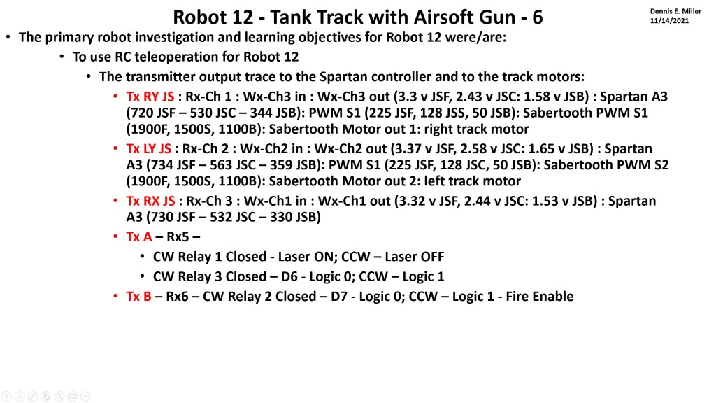
Demo 2 – Keyboard teleop –
>ros2 launch turtlebot3_bringup robot.launch.py
>ros2 run turtlebot3_teleop teleop_keyboard
Control Your TurtleBot3!
—————————
Moving around:
w
a s d
x
w/x : increase/decrease linear velocity (Burger : ~ 0.22, Waffle and
Waffle Pi : ~ 0.26)
a/d : increase/decrease angular velocity (Burger : ~ 2.84, Waffle and
Waffle Pi : ~ 1.82)
space key, s : force stop
CTRL-C to quit
currently: linear velocity 0.01 angular velocity 0.0
currently: linear velocity 0.02 angular velocity 0.0
currently: linear velocity 0.03 angular velocity 0.0
currently: linear velocity 0.04 angular velocity 0.0
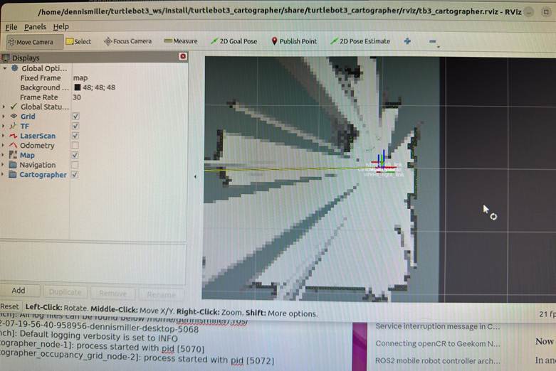
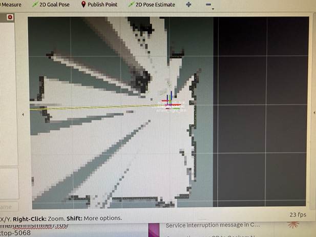
Demo 3 – SLAM mapping –
>ros2 launch turtlebot3_bringup robot.launch.py
>ros2 launch turtlebot3_cartographer cartographer.launch.py
[INFO] [launch]: All log files can be found below
/home/dennismiller/.ros/log/2026-02-07-19-56-40-958956-dennismiller-desktop-5068
[INFO] [launch]: Default logging verbosity is set to INFO
[INFO] [cartographer_node-1]: process started with pid [5070]
[INFO]
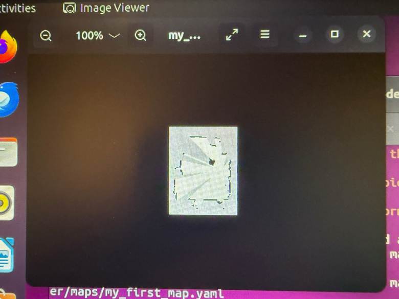
Demo 4 – Save map
>mkdir -p ~/maps
>ros2 run nav2_map_server map_saver_cli -f ~/maps/my_first_map
Saves two files:
- ~/maps/my_first_map.yaml — map metadata
- ~/maps/my_first_map.pgm — map image (grayscale)
View the map image – eog ~/maps/my_first_map.pgm
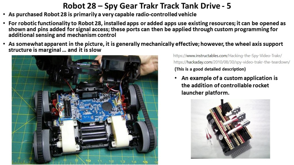
Demo 5 – Autonomous navigation
>ros2 launch turtlebot3_bringup rviz2.launch.py
>ros2 launch turtlebot3_navigation2 navigation2.launch.pymap:=$HOME/maps/my_first_map.yaml
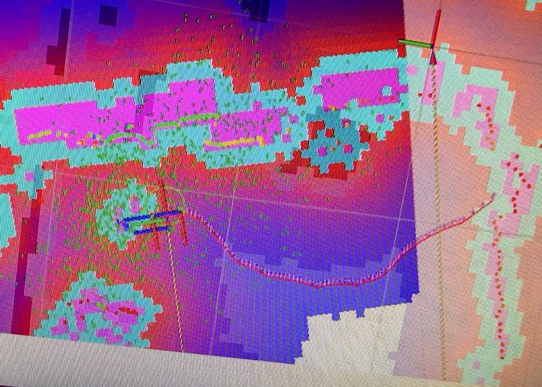
This command starts navigation and calls the SLAM map from the prior demo. As this opened, the responsiveness of the RPI 4 was very low; it was difficult to determine if selections were used. In the Rviz header, ‘2D Pose Estimate’ was selected and then the current position selected. ‘2D Goal Pose’ is was selected and then the desire position on the map was selected. A path was calculated as shown. The Turtlebots wheels were driven in an attempt to move it to the selected location. While the basic idea worked the combination of the slow response, selection uncertainty and physical setup didn’t result in the robot moving as shown.
RViz Navigation Explained
What you’re seeing:
| Color | What it is |
| Green particles | Robot’s estimated positions (localization uncertainty) |
| Blue line | Planned global path to goal |
| Red lines/areas | Costmap – obstacles and inflation zones (keep-out areas) |
| Black areas | Walls/obstacles from your saved map |
| Gray areas | Free space |
| White areas | Unknown space |
Demo 6 – ROS Topic list
>ros2 topic list
battery_state
/cmd_vel
/imu
/joint_states
/magnetic_field
/odom
/parameter_events
/robot_description
/rosout
/scan
/sensor_state
/tf
/tf_static
>dennismiller@dennismiller-desktop:~$ ros2 topic info /scan
Type: sensor_msgs/msg/LaserScan
Publisher count: 1
Subscription count: 0
>dennismiller@dennismiller-desktop:~$ ros2 topic hz /scan
WARNING: topic [/scan] does not appear to be published yet
average rate: 4.985
min: 0.200s max: 0.201s std dev: 0.00030s
window: 6 (Note: ‘window’ inidicates the number of messages sampled; it’s cummulative)
average rate: 4.984
min: 0.200s max: 0.201s std dev: 0.00033s
window: 11
average rate: 4.984
min: 0.199s max: 0.202s std dev: 0.00054s
…..
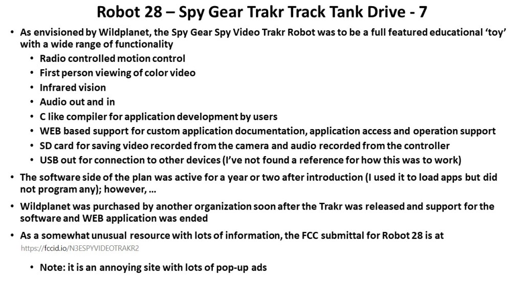
Demo 7 – LIDAR data
>ros2 launch turtlebot3_bringup rviz2.launch.py
>ros2 topic echo /scan –once
header:
stamp:
sec: 1770571607
nanosec: 524285835
frame_id: base_scan
angle_min: 0.0
angle_max: 6.2657318115234375
angle_increment: 0.01745329238474369
time_increment: 0.0005592841189354658
scan_time: 0.20134228467941284
range_min: 0.11999999731779099
range_max: 3.5
ranges:
– 0.4399999976158142
– 0.43299999833106995
– 0.4300000071525574
…..
LIDAR is publishing at 5 Hz (normal for LDS-01)
Key fields:
| Field | Meaning |
| angle_min / angle_max | Scan coverage (0 to 6.28 = 360°) |
| range_min / range_max | Valid distance range (0.12m to 3.5m) |
| ranges | Array of distances for each angle |
| intensities | Signal strength at each angle |
Demo 8 – Odometry data
>ros2 launch turtlebot3_bringup robot.launch.py
>ros2 topic echo /odom –once
stamp: sec: 1770572248 nanosec: 212764219
frame_id: odom
child_frame_id: base_footprint
pose:
pose:
position: x: 15.919378026437194 y: 0.33155781798783285 z: 0.0
orientation: x: 0.0 y: 0.0 z: 0.013453528466268046 w: 0.9999094971905244
covariance: – 0.0 – 0.0 – 0.0 – 0.0 – 0.0 – 0.0 – 0.0 – 0.0 – 0.0 – 0.0 – 0.0 – 0.0 – 0.0 – 0.0 – 0.0 – 0.0 – 0.0 – 0.0 – 0.0 – 0.0 – 0.0 – 0.0 – 0.0 – 0
Covariance is a 6×6 matrix (36 values) representing uncertainty in the measurement. It tells other nodes “how confident” the odometry is. 0.0 is ‘don’t know’/’not provided’, ~.001 high confidence, ~1+ low confidence.
Running the wheels with teleop resulted in :
Field Value Meaning
position.x 15.92 m Robot traveled ~16 meters
forwardposition.y 0.33 m Slight drift sideways
twist.linear.x 0.086 m/s Currently moving forward slowly
twist.angular.z -0.003 rad/s Tiny right turn
Key fields:
| Field | Meaning |
| pose.position.x | Distance traveled forward (meters) |
| pose.position.y | Distance traveled sideways (meters) |
| pose.orientation | Robot heading (quaternion) |
| twist.linear.x | Current forward velocity (m/s) |
| twist.angular.z | Current rotation rate (rad/s) |
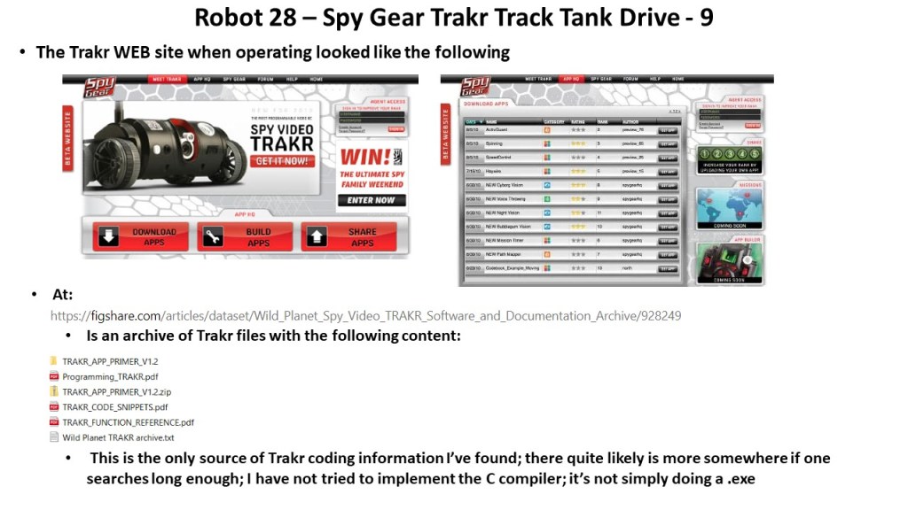
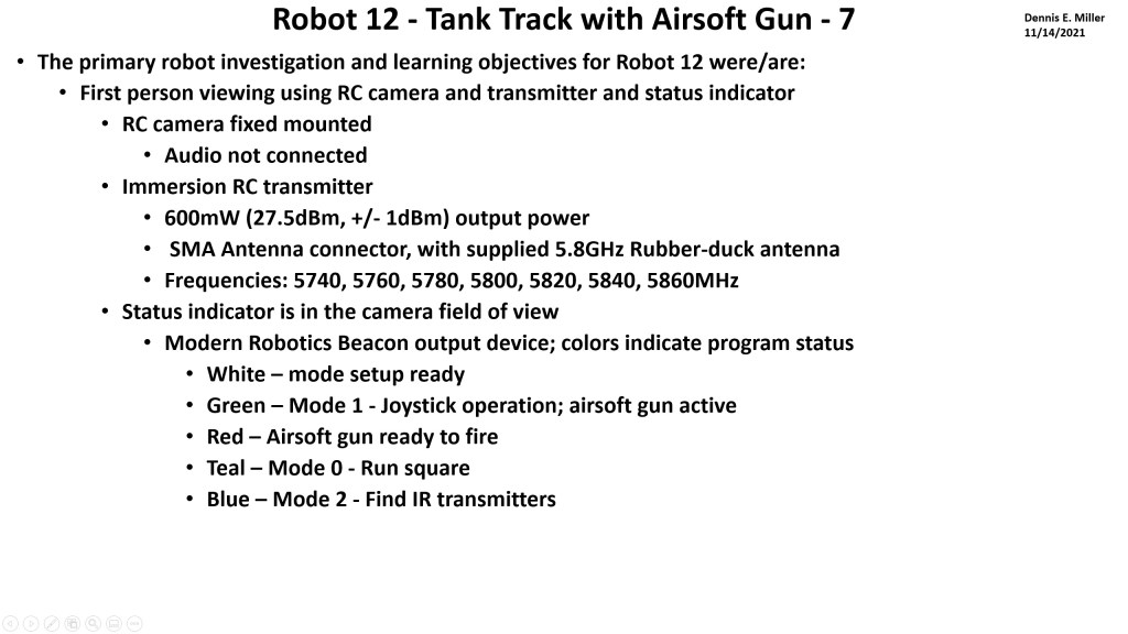
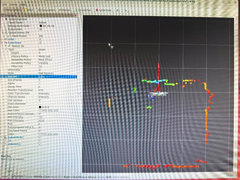
Demo 9 – Rviz visualization
Stop ROS and restart – >ros2 launch turtlebot3_bringup robot.launch.py
>ros2 launch turtlebot3_bringup rviz2.launch.py
Rviz with LIDAR data points; color is intensity
Demo 10 – System Status
# ROS2 version: >echo $TURTLEBOT3_MODEL – humble
# Active nodes: >ros2 node list –
# Active topics: >ros2 topic list –
# Active services: >ros2 service list –
# Sensor states: >ros2 topic echo /sensor_state –once –
# RPI 4 RAM: >free -h –
# RPI 4 SD Storage: >df -h –
# RPI 4 Temperature: >cat /sys/class/thermal/thermal_zone0/temp (divide by 1000 for C) –
# Serial Ports: >ls /dev/ttyACM0 /dev/ttyUSB0 –
ROS2 nodes:
>ros2 launch turtlebot3_bringup robot.launch.py
>ros2 node list
| Node | Purpose |
| /turtlebot3_node | Motor control, OpenCR communication |
| /hlds_laser_publisher | LiDAR driver (LDS-01) |
| /robot_state_publisher | Publishes robot URDF/transforms |
When Running Teleop
| Node | Purpose |
| /teleop_keyboard | Keyboard input → /cmd_vel |
When Running SLAM (Cartographer)
| Node | Purpose |
| /cartographer_node | SLAM processing |
| /cartographer_occupancy_grid_node | Generates map grid |
When Running Navigation
| Node | Purpose |
| /bt_navigator | Behavior tree executor |
| /controller_server | Path following |
| /planner_server | Path planning |
| /map_server | Serves the saved map |
| /amcl | Localization (particle filter) |
| /lifecycle_manager | Manages node states |
When Running RViz
| Node | Purpose |
| /rviz2 | Visualization |
Logitech Controller
Add Xbox/Microsoft Controller
Step 1: Install Xbox driver and joystick packages
bash
# Install Xbox controller driver
>sudo apt install xboxdrv joystick jstest-gtk
# Install ROS2 joystick packages
>sudo apt install ros-humble-joy ros-humble-teleop-twist-joy
Step 2: Connect controller and verify
bash
# Plug in Xbox controller via USB, then check
>ls /dev/input/js*
# Should show /dev/input/js0
# Test the controller
>jstest /dev/input/js0
# Or with GUI
>jstest-gtk
Step 3: Set permissions
bash
# Add user to input group
>sudo usermod -aG input $USER
# Create udev rule for controller
>echo ‘KERNEL==”js*”, MODE=”0666″‘ | sudo tee /etc/udev/rules.d/99-joystick.rules
>sudo udevadm control –reload-rules
>sudo udevadm trigger
Logout and login for group changes.
Step 4: Test with ROS2
Terminal 1 – Launch robot:
bash
>ros2 launch turtlebot3_bringup robot.launch.py
Terminal 2 – Launch joystick node:
bash
>ros2 run joy joy_node
Terminal 3 – Check joystick data:
bash
>ros2 topic echo /joy
Move sticks and press buttons – you should see values change.
Step 5: Launch teleop with joystick
Terminal 2 – Replace joy_node with full teleop:
bash
>ros2 launch teleop_twist_joy teleop-launch.py joy_config:=’xbox’
Controller Mapping (Xbox):
| Control | Action |
| Left stick up/down | Forward/backward |
| Right stick left/right | Turn left/right |
| LB (left bumper) | Hold to enable movement (deadman switch) |
| RB (right bumper) | Hold for turbo speed |
Step 6: Create a launch script
bash
>cat > ~/turtlebot3_demos/xbox_teleop.sh << ‘EOF’
#!/bin/bash
>source /opt/ros/humble/setup.bash
>source ~/turtlebot3_ws/install/setup.bash
>echo “Xbox Controller Teleop for TurtleBot3”
>echo “”
>echo “Controls:”
>echo ” Left stick : Forward/Backward”
>echo ” Right stick : Turn Left/Right”
>echo ” LB (hold) : Enable movement”
>echo ” RB (hold) : Turbo mode”
>echo “”
>echo “Make sure bringup is running first!”
>echo “”
>ros2 launch teleop_twist_joy teleop-launch.py joy_config:=’xbox’
>EOF
>chmod +x ~/turtlebot3_demos/xbox_teleop.sh
Duplicate SD card On Linux PC
# Insert SD card into PC, find the device name
>lsblk
# Usually shows as /dev/sdb or /dev/mmcblk0
# Make sure to identify the CORRECT device!
# Create image (replace sdX with your device)
>sudo dd if=/dev/sdX of=~/turtlebot3_backup.img bs=4M status=progress
# Compress it (optional, saves space)
>gzip ~/turtlebot3_backup.img
To restore to a new SD card:
# Decompress if needed
>gunzip ~/turtlebot3_backup.img.gz
# Write to new SD card (replace sdX)
>sudo dd if=~/turtlebot3_backup.img of=/dev/sdX bs=4M status=progress
Simulation with Gazebo
While technically feasible to run the Turtlebot 3 as a Gazebo simulation, the computational power required is really beyond the RPI 4B with 4 Gb of RAM. I didn’t try to run it.
Configuration Using Python Commands
The entire configuration process was done through a Python script that ran the required commands. For avid Python coders this is likely an obvious process. For me as a sometimes Python coder it was … amazing. The Python script follows.
#!/bin/bash
#===============================================================================
# TurtleBot3 Setup Script for Raspberry Pi 4 with Ubuntu 22.04 and ROS2
Humble
#
# This script performs:
# 1. RPi 4 System Characteristics Detection
# 2. ROS2 Humble Installation
# 3. TurtleBot3 Packages and Demo Scripts Installation
#
# Usage: chmod +x turtlebot3_rpi4_setup.sh && ./turtlebot3_rpi4_setup.sh
#===============================================================================
set -e # Exit on error
# Colors for output
RED=’\033[0;31m’
GREEN=’\033[0;32m’
YELLOW=’\033[1;33m’
BLUE=’\033[0;34m’
NC=’\033[0m’ # No Color
print_header() {
echo -e
“\n${BLUE}============================================================${NC}”
echo -e “${BLUE}$1${NC}”
echo -e
“${BLUE}============================================================${NC}\n”
}
print_success() {
echo -e “${GREEN}✓ $1${NC}”
}
print_warning() {
echo -e “${YELLOW}⚠ $1${NC}”
}
print_error() {
echo -e “${RED}✗ $1${NC}”
}
#===============================================================================
# PART 1: RASPBERRY PI 4 SYSTEM CHARACTERISTICS
#===============================================================================
detect_rpi4_characteristics() {
print_header “PART 1: RASPBERRY PI 4 SYSTEM CHARACTERISTICS”
OUTPUT_FILE=”$HOME/rpi4_characteristics.txt”
echo “Raspberry Pi 4 System Characteristics Report” > “$OUTPUT_FILE”
echo “Generated: $(date)” >> “$OUTPUT_FILE”
echo “=============================================” >> “$OUTPUT_FILE”
# CPU Information
echo -e “\n${GREEN}— CPU Information —${NC}”
echo -e “\nCPU Information:” >> “$OUTPUT_FILE”
if [ -f /proc/cpuinfo ]; then
CPU_MODEL=$(grep “Model” /proc/cpuinfo | head -1 | cut -d: -f2
| xargs)
CPU_HARDWARE=$(grep “Hardware” /proc/cpuinfo | head -1 | cut
-d: -f2 | xargs)
CPU_REVISION=$(grep “Revision” /proc/cpuinfo | head -1 | cut
-d: -f2 | xargs)
CPU_CORES=$(nproc)
echo ” Model: $CPU_MODEL”
echo ” Hardware: $CPU_HARDWARE”
echo ” Revision: $CPU_REVISION”
echo ” CPU Cores: $CPU_CORES”
echo ” Model: $CPU_MODEL” >> “$OUTPUT_FILE”
echo ” Hardware: $CPU_HARDWARE” >> “$OUTPUT_FILE”
echo ” Revision: $CPU_REVISION” >> “$OUTPUT_FILE”
echo ” CPU Cores: $CPU_CORES” >> “$OUTPUT_FILE”
fi
# CPU Architecture
ARCH=$(uname -m)
echo ” Architecture: $ARCH”
echo ” Architecture: $ARCH” >> “$OUTPUT_FILE”
# CPU Frequency
if [ -f /sys/devices/system/cpu/cpu0/cpufreq/cpuinfo_max_freq ]; then
MAX_FREQ=$(cat
/sys/devices/system/cpu/cpu0/cpufreq/cpuinfo_max_freq)
MAX_FREQ_MHZ=$((MAX_FREQ / 1000))
echo ” Max CPU Frequency: ${MAX_FREQ_MHZ} MHz”
echo ” Max CPU Frequency: ${MAX_FREQ_MHZ} MHz” >> “$OUTPUT_FILE”
fi
# Memory Information
echo -e “\n${GREEN}— Memory Information —${NC}”
echo -e “\nMemory Information:” >> “$OUTPUT_FILE”
TOTAL_MEM=$(free -h | grep Mem | awk ‘{print $2}’)
USED_MEM=$(free -h | grep Mem | awk ‘{print $3}’)
FREE_MEM=$(free -h | grep Mem | awk ‘{print $4}’)
echo ” Total RAM: $TOTAL_MEM”
echo ” Used RAM: $USED_MEM”
echo ” Free RAM: $FREE_MEM”
echo ” Total RAM: $TOTAL_MEM” >> “$OUTPUT_FILE”
echo ” Used RAM: $USED_MEM” >> “$OUTPUT_FILE”
echo ” Free RAM: $FREE_MEM” >> “$OUTPUT_FILE”
# Storage Information
echo -e “\n${GREEN}— Storage Information —${NC}”
echo -e “\nStorage Information:” >> “$OUTPUT_FILE”
df -h / | tail -1 | while read filesystem size used avail use_pct
mounted; do
echo ” Root Filesystem: $filesystem”
echo ” Total Size: $size”
echo ” Used: $used ($use_pct)”
echo ” Available: $avail”
echo ” Root Filesystem: $filesystem” >> “$OUTPUT_FILE”
echo ” Total Size: $size” >> “$OUTPUT_FILE”
echo ” Used: $used ($use_pct)” >> “$OUTPUT_FILE”
echo ” Available: $avail” >> “$OUTPUT_FILE”
done
# Temperature
echo -e “\n${GREEN}— Temperature —${NC}”
echo -e “\nTemperature:” >> “$OUTPUT_FILE”
if [ -f /sys/class/thermal/thermal_zone0/temp ]; then
TEMP=$(cat /sys/class/thermal/thermal_zone0/temp)
TEMP_C=$(echo “scale=1; $TEMP / 1000” | bc)
echo ” CPU Temperature: ${TEMP_C}°C”
echo ” CPU Temperature: ${TEMP_C}°C” >> “$OUTPUT_FILE”
fi
# GPU Memory (if vcgencmd available)
if command -v vcgencmd &> /dev/null; then
echo -e “\n${GREEN}— GPU Information —${NC}”
echo -e “\nGPU Information:” >> “$OUTPUT_FILE”
GPU_MEM=$(vcgencmd get_mem gpu 2>/dev/null || echo “N/A”)
echo ” $GPU_MEM”
echo ” $GPU_MEM” >> “$OUTPUT_FILE”
fi
# OS Information
echo -e “\n${GREEN}— Operating System —${NC}”
echo -e “\nOperating System:” >> “$OUTPUT_FILE”
if [ -f /etc/os-release ]; then
source /etc/os-release
echo ” OS: $PRETTY_NAME”
echo ” Kernel: $(uname -r)”
echo ” OS: $PRETTY_NAME” >> “$OUTPUT_FILE”
echo ” Kernel: $(uname -r)” >> “$OUTPUT_FILE”
fi
# Network Interfaces
echo -e “\n${GREEN}— Network Interfaces —${NC}”
echo -e “\nNetwork Interfaces:” >> “$OUTPUT_FILE”
ip -o link show | while read num iface rest; do
IFACE_NAME=$(echo $iface | tr -d ‘:’)
if [[ “$IFACE_NAME” != “lo” ]]; then
IP_ADDR=$(ip -4 addr show $IFACE_NAME 2>/dev/null | grep
inet | awk ‘{print $2}’ | head -1)
if [ -n “$IP_ADDR” ]; then
echo ” $IFACE_NAME: $IP_ADDR”
echo ” $IFACE_NAME: $IP_ADDR” >> “$OUTPUT_FILE”
fi
fi
done
# USB Devices
echo -e “\n${GREEN}— USB Devices —${NC}”
echo -e “\nUSB Devices:” >> “$OUTPUT_FILE”
if command -v lsusb &> /dev/null; then
lsusb | while read line; do
echo ” $line”
echo ” $line” >> “$OUTPUT_FILE”
done
fi
# Serial Ports (important for TurtleBot)
echo -e “\n${GREEN}— Serial Ports (for OpenCR) —${NC}”
echo -e “\nSerial Ports:” >> “$OUTPUT_FILE”
ls -la /dev/ttyACM* /dev/ttyUSB* 2>/dev/null | while read line; do
echo ” $line”
echo ” $line” >> “$OUTPUT_FILE”
done || echo ” No serial ports detected”
print_success “Characteristics saved to: $OUTPUT_FILE”
}
#===============================================================================
# PART 2: ROS2 HUMBLE INSTALLATION
#===============================================================================
install_ros2_humble() {
print_header “PART 2: ROS2 HUMBLE INSTALLATION”
# Check if ROS2 is already installed
if [ -d “/opt/ros/humble” ]; then
print_warning “ROS2 Humble appears to be already installed at
/opt/ros/humble”
read -p “Do you want to reinstall? (y/N): ” REINSTALL
if [[ ! “$REINSTALL” =~ ^[Yy]$ ]]; then
print_success “Skipping ROS2 installation”
return
fi
fi
echo “Setting up locale…”
sudo apt update && sudo apt install -y locales
sudo locale-gen en_US en_US.UTF-8
sudo update-locale LC_ALL=en_US.UTF-8 LANG=en_US.UTF-8
export LANG=en_US.UTF-8
print_success “Locale configured”
echo “Adding ROS2 repository…”
sudo apt install -y software-properties-common
sudo add-apt-repository -y universe
sudo apt update && sudo apt install -y curl gnupg lsb-release
sudo curl -sSL
https://raw.githubusercontent.com/ros/rosdistro/master/ros.key \
-o /usr/share/keyrings/ros-archive-keyring.gpg
echo “deb
[arch=$(dpkg –print-architecture)
signed-by=/usr/share/keyrings/ros-archive-keyring.gpg]
\
http://packages.ros.org/ros2/ubuntu $(source /etc/os-release &&
echo $UBUNTU_CODENAME) main” | \
sudo tee /etc/apt/sources.list.d/ros2.list > /dev/null
print_success “ROS2 repository added”
echo “Updating package lists…”
sudo apt update
sudo apt upgrade -y
echo “Installing ROS2 Humble…”
# For RPi without display, use ros-base. With display, use desktop
read -p “Install with GUI tools (desktop) or minimal (ros-base)?
[desktop/base]: ” ROS_TYPE
if [[ “$ROS_TYPE” == “desktop” ]]; then
sudo apt install -y ros-humble-desktop
print_success “ROS2 Humble Desktop installed”
else
sudo apt install -y ros-humble-ros-base
print_success “ROS2 Humble Base installed”
fi
# Install development tools
echo “Installing development tools…”
sudo apt install -y ros-dev-tools python3-colcon-common-extensions
python3-rosdep
print_success “Development tools installed”
# Initialize rosdep
if [ ! -f /etc/ros/rosdep/sources.list.d/20-default.list ]; then
echo “Initializing rosdep…”
sudo rosdep init
fi
rosdep update
print_success “rosdep initialized”
# Add ROS2 to bashrc
if ! grep -q “source /opt/ros/humble/setup.bash” ~/.bashrc; then
echo “source /opt/ros/humble/setup.bash” >> ~/.bashrc
print_success “ROS2 added to .bashrc”
fi
# Source for current session
source /opt/ros/humble/setup.bash
print_success “ROS2 Humble installation complete!”
}
#===============================================================================
# PART 3: TURTLEBOT3 PACKAGES AND DEMOS
#===============================================================================
install_turtlebot3() {
print_header “PART 3: TURTLEBOT3 PACKAGES AND DEMOS”
# Source ROS2
source /opt/ros/humble/setup.bash
# Determine TurtleBot3 model
echo “Which TurtleBot3 model do you have?”
echo ” 1) burger”
echo ” 2) waffle”
echo ” 3) waffle_pi”
read -p “Enter choice [1-3]: ” TB3_CHOICE
case $TB3_CHOICE in
1) TB3_MODEL=”burger” ;;
2) TB3_MODEL=”waffle” ;;
3) TB3_MODEL=”waffle_pi” ;;
*) TB3_MODEL=”burger” ;;
esac
# Determine LiDAR model
echo “Which LiDAR model do you have?”
echo ” 1) LDS-01 (older TurtleBot3)”
echo ” 2) LDS-02 (newer TurtleBot3)”
read -p “Enter choice [1-2]: ” LDS_CHOICE
case $LDS_CHOICE in
1) LDS_MODEL=”LDS-01″ ;;
2) LDS_MODEL=”LDS-02″ ;;
*) LDS_MODEL=”LDS-01″ ;;
esac
# Install TurtleBot3 dependencies
echo “Installing TurtleBot3 dependencies…”
sudo apt install -y \
ros-humble-cartographer \
ros-humble-cartographer-ros \
ros-humble-navigation2 \
ros-humble-nav2-bringup \
ros-humble-dynamixel-sdk \
ros-humble-turtlebot3-msgs \
ros-humble-turtlebot3
print_success “TurtleBot3 base packages installed”
# Create TurtleBot3 workspace
echo “Creating TurtleBot3 workspace…”
mkdir -p ~/turtlebot3_ws/src
cd ~/turtlebot3_ws/src
# Clone TurtleBot3 packages from source for latest updates
echo “Cloning TurtleBot3 source packages…”
if [ ! -d “DynamixelSDK” ]; then
git clone -b humble https://github.com/ROBOTIS-GIT/DynamixelSDK.git
fi
if [ ! -d “turtlebot3_msgs” ]; then
git clone -b humble
https://github.com/ROBOTIS-GIT/turtlebot3_msgs.git
fi
if [ ! -d “turtlebot3” ]; then
git clone -b humble https://github.com/ROBOTIS-GIT/turtlebot3.git
fi
if [ ! -d “turtlebot3_simulations” ]; then
git clone -b humble-devel
https://github.com/ROBOTIS-GIT/turtlebot3_simulations.git
fi
# Install LiDAR driver based on model
echo “Installing LiDAR driver…”
if [ ! -d “ld08_driver” ] && [ “$LDS_MODEL” == “LDS-02” ]; then
git clone -b ros2-devel
https://github.com/ROBOTIS-GIT/ld08_driver.git
elif [ ! -d “hls_lfcd_lds_driver” ] && [ “$LDS_MODEL” == “LDS-01”
]; then
git clone -b ros2-devel
https://github.com/ROBOTIS-GIT/hls_lfcd_lds_driver.git
fi
print_success “Source packages cloned”
# Install dependencies with rosdep
echo “Installing dependencies with rosdep…”
cd ~/turtlebot3_ws
rosdep install –from-paths src –ignore-src -r -y || true
# Build workspace
echo “Building TurtleBot3 workspace (this may take a while on RPi)…”
cd ~/turtlebot3_ws
colcon build –symlink-install –parallel-workers 2
print_success “TurtleBot3 workspace built”
# Add TurtleBot3 environment to bashrc
echo “Configuring environment…”
# Remove old entries if they exist
sed -i ‘/TURTLEBOT3_MODEL/d’ ~/.bashrc
sed -i ‘/LDS_MODEL/d’ ~/.bashrc
sed -i ‘/ROS_DOMAIN_ID.*TURTLEBOT/d’ ~/.bashrc
sed -i ‘/turtlebot3_ws/d’ ~/.bashrc
# Add new entries
cat >> ~/.bashrc << EOF
# TurtleBot3 Configuration
source ~/turtlebot3_ws/install/setup.bash
export TURTLEBOT3_MODEL=$TB3_MODEL
export LDS_MODEL=$LDS_MODEL
export ROS_DOMAIN_ID=30 # Match this with Remote PC
export OPENCR_PORT=/dev/ttyACM0
export OPENCR_MODEL=$TB3_MODEL
EOF
print_success “Environment configured in .bashrc”
# Set up udev rules for OpenCR and LiDAR
echo “Setting up udev rules for hardware…”
# OpenCR udev rule
sudo bash -c ‘cat > /etc/udev/rules.d/99-opencr.rules << EOF
ATTRS{idVendor}==”0483″, ATTRS{idProduct}==”5740″,
ENV{ID_MM_DEVICE_IGNORE}=”1″, MODE=”0666″, GROUP=”dialout”,
SYMLINK+=”opencr”
EOF’
# LiDAR udev rule
if [ “$LDS_MODEL” == “LDS-01” ]; then
sudo bash -c ‘cat > /etc/udev/rules.d/99-lds01.rules << EOF
KERNEL==”ttyUSB*”, ATTRS{idVendor}==”0483″, ATTRS{idProduct}==”5740″,
MODE=”0666″, GROUP=”dialout”, SYMLINK+=”ttyLDS”
EOF’
else
sudo bash -c ‘cat > /etc/udev/rules.d/99-lds02.rules << EOF
KERNEL==”ttyUSB*”, ATTRS{idVendor}==”10c4″, ATTRS{idProduct}==”ea60″,
MODE=”0666″, GROUP=”dialout”, SYMLINK+=”ttyLDS”
EOF’
fi
# Reload udev rules
sudo udevadm control –reload-rules
sudo udevadm trigger
# Add user to dialout group
sudo usermod -aG dialout $USER
print_success “udev rules configured”
# Create demo launch scripts
create_demo_scripts
print_success “TurtleBot3 installation complete!”
}
#===============================================================================
# CREATE DEMO SCRIPTS
#===============================================================================
create_demo_scripts() {
print_header “Creating TurtleBot3 Demo Scripts”
DEMO_DIR=”$HOME/turtlebot3_demos”
mkdir -p “$DEMO_DIR”
# Demo 1: Bringup (run on TurtleBot)
cat > “$DEMO_DIR/01_bringup.sh” << ‘EOF’
#!/bin/bash
# TurtleBot3 Bringup – Run this on the TurtleBot3 (RPi)
# This starts the robot’s core systems: motors, sensors, etc.
source /opt/ros/humble/setup.bash
source ~/turtlebot3_ws/install/setup.bash
echo “Starting TurtleBot3 Bringup…”
echo “Model: $TURTLEBOT3_MODEL”
echo “LiDAR: $LDS_MODEL”
echo “”
echo “Press Ctrl+C to stop”
ros2 launch turtlebot3_bringup robot.launch.py
EOF
chmod +x “$DEMO_DIR/01_bringup.sh”
# Demo 2: Teleop Keyboard
cat > “$DEMO_DIR/02_teleop_keyboard.sh” << ‘EOF’
#!/bin/bash
# Keyboard Teleoperation – Control TurtleBot3 with keyboard
# Run this on Remote PC or TurtleBot
source /opt/ros/humble/setup.bash
source ~/turtlebot3_ws/install/setup.bash
echo “Keyboard Teleoperation for TurtleBot3”
echo “”
echo “Controls:”
echo ” w/x : increase/decrease linear velocity”
echo ” a/d : increase/decrease angular velocity”
echo ” space/s : stop”
echo “”
ros2 run turtlebot3_teleop teleop_keyboard
EOF
chmod +x “$DEMO_DIR/02_teleop_keyboard.sh”
# Demo 3: SLAM (Cartographer)
cat > “$DEMO_DIR/03_slam_cartographer.sh” << ‘EOF’
#!/bin/bash
# SLAM with Cartographer – Create a map while driving
# Run on Remote PC while bringup is running on TurtleBot
source /opt/ros/humble/setup.bash
source ~/turtlebot3_ws/install/setup.bash
echo “Starting SLAM with Cartographer…”
echo “Make sure bringup is running on TurtleBot3”
echo “”
ros2 launch turtlebot3_cartographer cartographer.launch.py
EOF
chmod +x “$DEMO_DIR/03_slam_cartographer.sh”
# Demo 4: Save Map
cat > “$DEMO_DIR/04_save_map.sh” << ‘EOF’
#!/bin/bash
# Save the map created by SLAM
# Run this after exploring the environment
source /opt/ros/humble/setup.bash
MAP_NAME=${1:-“my_map”}
echo “Saving map as: $MAP_NAME”
ros2 run nav2_map_server map_saver_cli -f ~/maps/$MAP_NAME
echo “Map saved to ~/maps/$MAP_NAME.yaml and ~/maps/$MAP_NAME.pgm”
EOF
chmod +x “$DEMO_DIR/04_save_map.sh”
# Demo 5: Navigation
cat > “$DEMO_DIR/05_navigation.sh” << ‘EOF’
#!/bin/bash
# Autonomous Navigation – Navigate using a saved map
# Run on Remote PC
source /opt/ros/humble/setup.bash
source ~/turtlebot3_ws/install/setup.bash
MAP_FILE=${1:-“$HOME/maps/my_map.yaml”}
echo “Starting Navigation with map: $MAP_FILE”
echo “Make sure bringup is running on TurtleBot3”
echo “”
ros2 launch turtlebot3_navigation2 navigation2.launch.py map:=$MAP_FILE
EOF
chmod +x “$DEMO_DIR/05_navigation.sh”
# Demo 6: Check Topics
cat > “$DEMO_DIR/06_check_topics.sh” << ‘EOF’
#!/bin/bash
# List all active ROS2 topics
# Useful for debugging
source /opt/ros/humble/setup.bash
echo “Active ROS2 Topics:”
echo “===================”
ros2 topic list
echo “”
echo “To see topic data, use: ros2 topic echo /topic_name”
echo “To see topic info, use: ros2 topic info /topic_name”
EOF
chmod +x “$DEMO_DIR/06_check_topics.sh”
# Demo 7: View LiDAR Data
cat > “$DEMO_DIR/07_view_lidar.sh” << ‘EOF’
#!/bin/bash
# View LiDAR scan data
# Run while bringup is active
source /opt/ros/humble/setup.bash
echo “Viewing LiDAR data from /scan topic”
echo “Press Ctrl+C to stop”
echo “”
ros2 topic echo /scan
EOF
chmod +x “$DEMO_DIR/07_view_lidar.sh”
# Demo 8: View Odometry
cat > “$DEMO_DIR/08_view_odom.sh” << ‘EOF’
#!/bin/bash
# View odometry data
# Run while bringup is active
source /opt/ros/humble/setup.bash
echo “Viewing Odometry data from /odom topic”
echo “Press Ctrl+C to stop”
echo “”
ros2 topic echo /odom
EOF
chmod +x “$DEMO_DIR/08_view_odom.sh”
# Demo 9: RViz Visualization (for Remote PC with display)
cat > “$DEMO_DIR/09_rviz.sh” << ‘EOF’
#!/bin/bash
# Launch RViz for visualization
# Run on Remote PC with display
source /opt/ros/humble/setup.bash
source ~/turtlebot3_ws/install/setup.bash
echo “Launching RViz…”
ros2 launch turtlebot3_bringup rviz2.launch.py
EOF
chmod +x “$DEMO_DIR/09_rviz.sh”
# Demo 10: System Status
cat > “$DEMO_DIR/10_system_status.sh” << ‘EOF’
#!/bin/bash
# Check ROS2 system status
source /opt/ros/humble/setup.bash
echo “ROS2 System Status”
echo “==================”
echo “”
echo “ROS2 Version:”
ros2 –version
echo “”
echo “Active Nodes:”
ros2 node list
echo “”
echo “Active Topics:”
ros2 topic list
echo “”
echo “Active Services:”
ros2 service list
EOF
chmod +x “$DEMO_DIR/10_system_status.sh”
# Create README for demos
cat > “$DEMO_DIR/README.md” << EOF
# TurtleBot3 Demo Scripts
## Quick Start
### On TurtleBot3 (Raspberry Pi):
1. First, run bringup:
\`\`\`
./01_bringup.sh
\`\`\`
### On Remote PC (or another terminal):
2. Control with keyboard:
\`\`\`
./02_teleop_keyboard.sh
\`\`\`
## Available Demos
| Script | Description | Run On |
|——–|————-|——–|
| 01_bringup.sh | Start robot systems | TurtleBot3 |
| 02_teleop_keyboard.sh | Keyboard control | Remote PC |
| 03_slam_cartographer.sh | Create map while driving | Remote PC |
| 04_save_map.sh | Save SLAM map | Remote PC |
| 05_navigation.sh | Autonomous navigation | Remote PC |
| 06_check_topics.sh | List ROS2 topics | Any |
| 07_view_lidar.sh | View LiDAR data | Any |
| 08_view_odom.sh | View odometry | Any |
| 09_rviz.sh | Visual monitoring | Remote PC (GUI) |
| 10_system_status.sh | Check system status | Any |
## Network Setup
Make sure TurtleBot3 and Remote PC are on the same network and have
matching:
– ROS_DOMAIN_ID (default: 30)
– Same ROS2 version (Humble)
## Troubleshooting
1. **Can’t connect to robot**: Check ROS_DOMAIN_ID matches
2. **No LiDAR data**: Check USB connection and udev rules
3. **Motors not moving**: Check OpenCR connection (/dev/ttyACM0)
## Environment Variables
Current configuration (in ~/.bashrc):
– TURTLEBOT3_MODEL=$TB3_MODEL
– LDS_MODEL=$LDS_MODEL
– ROS_DOMAIN_ID=30
EOF
# Create maps directory
mkdir -p ~/maps
print_success “Demo scripts created in: $DEMO_DIR”
echo “”
echo “Available demo scripts:”
ls -la “$DEMO_DIR”/*.sh
}
#===============================================================================
# MAIN MENU
#===============================================================================
main_menu() {
clear
echo -e “${BLUE}”
echo “╔══════════════════════════════════════════════════════════════╗”
echo “║ TurtleBot3 Setup for Raspberry Pi 4 + Ubuntu 22.04 ║”
echo “║ with ROS2 Humble ║”
echo “╚══════════════════════════════════════════════════════════════╝”
echo -e “${NC}”
echo “”
echo “Select an option:”
echo “”
echo ” 1) Run ALL steps (recommended for fresh install)”
echo ” 2) Part 1 only: Detect RPi4 characteristics”
echo ” 3) Part 2 only: Install ROS2 Humble”
echo ” 4) Part 3 only: Install TurtleBot3 packages & demos”
echo ” 5) Exit”
echo “”
read -p “Enter choice [1-5]: ” CHOICE
case $CHOICE in
1)
detect_rpi4_characteristics
install_ros2_humble
install_turtlebot3
;;
2)
detect_rpi4_characteristics
;;
3)
install_ros2_humble
;;
4)
install_turtlebot3
;;
5)
echo “Exiting…”
exit 0
;;
*)
echo “Invalid choice”
exit 1
;;
esac
}
#===============================================================================
# FINAL SUMMARY
#===============================================================================
print_final_summary() {
print_header “SETUP COMPLETE!”
echo “Summary of installed components:”
echo “”
echo ” 1. RPi4 Characteristics: ~/rpi4_characteristics.txt”
echo ” 2. ROS2 Humble: /opt/ros/humble/”
echo ” 3. TurtleBot3 Workspace: ~/turtlebot3_ws/”
echo ” 4. Demo Scripts: ~/turtlebot3_demos/”
echo “”
echo “Next steps:”
echo “”
echo ” 1. Log out and log back in (or reboot) for group changes”
echo ” 2. Connect your TurtleBot3 hardware”
echo ” 3. Run: cd ~/turtlebot3_demos && ./01_bringup.sh”
echo “”
echo “For keyboard control, open another terminal and run:”
echo ” cd ~/turtlebot3_demos && ./02_teleop_keyboard.sh”
echo “”
print_success “Happy robotics!”
}
#===============================================================================
# RUN SCRIPT
#===============================================================================
main_menu
print_final_summary