Comment on Getting Started Again
When I started this blog site a couple of years ago, I had a plan, but time and other interests got in the way. I’m ready to try this again with perhaps a little less rigorous view of what I want to write about. As before, my primary mobile robot blog objectives are to relate descriptions and comments on 1) the range of mobile robots I am working on; 2) supporting devices such as sensors, actuators, cameras … and 3) types of applications. My prior plan was to specifically work through a set of example robot types and implementations. At least for the present, my plan for topics is to describe what I’m working on and document descriptions, resources, things that work and don’t work and uses. Currently my interest and work are on the many, many sensors that are available and supported by the Arduino computers. Most will relate to mobile robots in some way; some will be applicable to topics outside of robotics. Sometimes topics will be in an orderly sequence and sometimes simply as I get to them. For a reader this is not ideal … but that’s the way I’m doing it.
This blog is essentially about things learned and implemented as a retired electrical engineer with at least a moderate amount of time and monetary resources. My general view is that if I haven’t at least implemented an example (not necessarily a pretty example) and learned from it, I won’t include it. That being said, only so much time and money is available and at some point, the effort on a topic (robots) becomes good enough (i.e., that’s all I care to know) or I have run up to the edge of my expertise or that which can be reasonably learned.
Nothing I include is intended to represent a basis for commercial or industrial design or production.
Where I might say a device or software doesn’t work, it is totally within my scope of development and test. It may be, and quite likely is that it does work in some context and that I can’t make it work in mine or don’t want to spend any more time trying. I will try to relate to a reasonable level, the basis of my conclusion.
Beginning on Sensors
This blog is titled ‘ … Sensors (1) – BME 280’. One of my activities is volunteering as a teaching naturalist at the Wehr Nature Center which is a unit of the Milwaukee County Park system. As a possible direction of instruction, the use of small computers and, primarily, environmental sensors to both study aspects of nature and also the basics of computers, sensing and data acquisition. Investigation this idea led to the accumulation of many different sensors which are applicable to the Nature Center’s objective. Also, many of these same sensors are applicable to the control, guidance and the mission of mobile robots. The primary small computer used is the Arduino in a number of forms. Sensor acquisition is an on-going process. There are lots of sensors. There are numbers of base suppliers or labels. These products are then sold through suppliers such as Amazon, Robot Shop, Digi-key and others. For most sensors, the base suppliers implement their version of the ‘chip’ or ‘package’ level sensor which come from electronic device manufacturer such as Texas Instruments, Bosch and others.
BME 280 Sensor Example
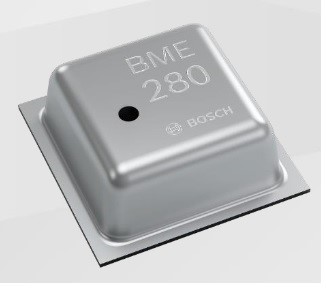
The BME 280 is manufactured by BOSCH (https://pdf1.alldatasheet.com/datasheet-pdf/view/1132060/BOSCH/BME280.html). It is a mechatronics device and measures temperature (0 degrees C to 65 C), relative humidity (20 to 80 % RH) and pressure (300 to 1100 hPa; 4 to 16 psi). There are of course lots of qualifiers and secondary specifications in the 55-page specification. The supply voltage is 1.7 to 3.6. Output communication is via I2C (Inter-Integrated Circuit) or SPI (Serial Peripheral Interface). The I2C address is 0x76.
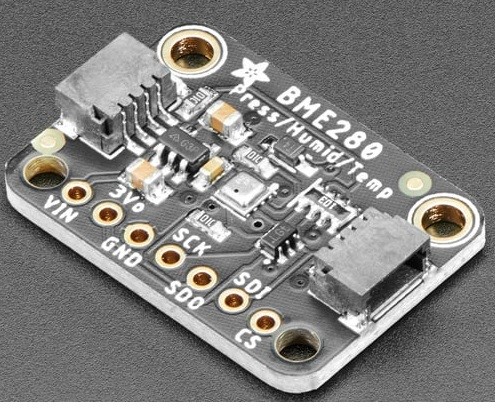
Adafruit (https://www.adafruit.com/product/2652) and others put the BOSCH BME280 on a printed circuit board with supporting power and communication electronics and sells it as an Arduino or other computer mountable and connectable sensor. I don’t have price data on the raw BME280 sensor; however, the Adafruit board is approximately $15 with the supportive additions. Adafruit also provides (usually) Arduino (and other computers) loadable software for BME280 functions in a program. The software provides user effective program commands through interface to the BME280 commands plus the driver (BOSCH).
There will be more on the software handling later.
Other like suppliers are SeeedStudio/Grove (https://www.seeedstudio.com/Grove-BME280-Environmental-Sensor-Temperature-Humidity-Barometer.html), WaveShare (https://www.waveshare.com/wiki/BME280_Environmental_Sensor), SparkFun (https://www.sparkfun.com/products/13676), HiLetgo (http://hiletgo.com/ProductDetail/1953483.html), DFRobot Gravity and Fermion (https://www.dfrobot.com/search-bme280.html) and there are probably others. Each vendor provides application software which is all similar and may be interchangeable but may include unique functions for that vendor. In addition, other software writers may provide their own versions. Generally, these are available on ‘GitHub’.
Arduino Test Platform
As a base for testing environmental related sensors as well as other aspects of Arduino devices, a board was layed out and built which included the following: Arduino Mega 2650 Rev 3; Gravity; IO Sensor Shield; 4×4 digital input keyboard; I2C 4 x 20 LCD display; I2C real time clock; I2C 3 color LED; cadmium sulphide analog light sensor (upper left corner); mechanical switch (low left corner); analog temperature sensor (middle right); ADXL 345 Adafruit I2C accelerometer board (under BME 280); and … an Adafruit BME280 board.
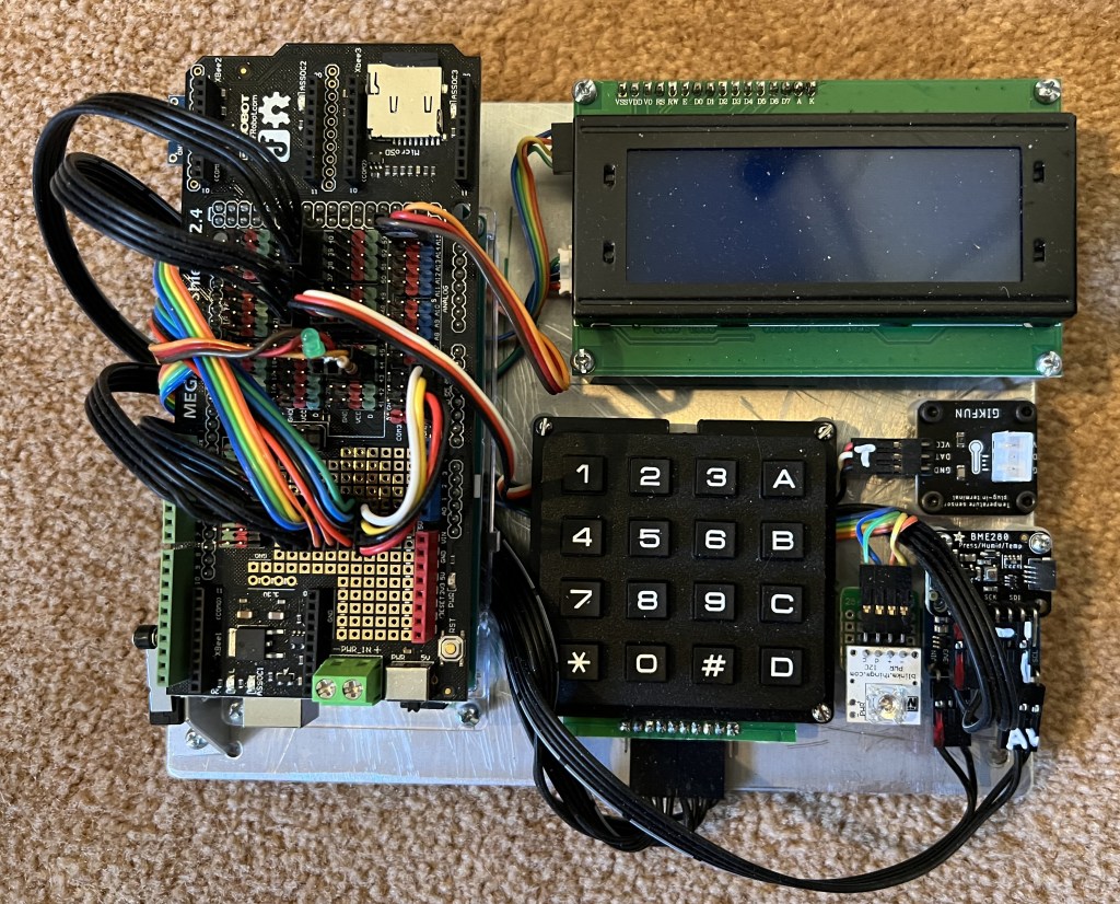
This board was constructed to provide a prototype student exercise board for learning about basic computer operation, data collections and sensor monitoring. The IO sensor shield board includes a micro-SD socket for data acquisition. There will be more discussion in the future of the components and configuration of this and related computer boards. The BME280 board is connected to the Arduino through the I2C socket hub in the prototyping section of the IO sensor shield.
Arduino Software for the BME280 and Testing
At the present (12/5/22) I have loaded Arduino IDE 2.0.3 (https://docs.arduino.cc/software/ide-v2/tutorials/getting-started/ide-v2-downloading-and-installing). A search of the IDE library results in 18 includes supporting the BME280. There are includes by Adafruit and SparkFun. The rest are names of Arduino software support organizations or individuals. Adafruit and SparkFun are installed.
To make the BME280 test more complete (and interesting), additional devices of the test board are used. The keypad for command; the display for information; the IO sensor shield SD card for data acquisition; and the RTC for timing. The process will be to build up to the final program by adding each of the components to complete the test board.
4×20 LCD I2C Display
At ‘Tools/Manage Libraries…’ opens the Library Manager. Searching on ‘LiquidCrystal’ gives a list of liquid crystal display includes. The main one is ‘LiquidCrystal by Arduino, Adafruit’ version 1.0.7 (latest, 12/4/22). This is installed and shows up in the ‘Sketch/Include Library’ as ‘LiquidCrystal.h’. However, this include is for a digital selection connected display. For an I2C connected display ‘include’, search for that. The result is about 33 includes. Which is best?? At https://www.arduino.cc/reference/en/libraries/liquidcrystal-i2c/ the Arduino library include is by Frank de Brabander. Searching for ‘Frank’ finds this include. This WEB site lists the include functions. When installed it is listed as ‘LiquidCrystal_I2C.h’. Finally, a bit of code is needed to test the I2C controlled liquid crystal display. There are numbers of options. One is to go to ‘more info’ in the Manage Libraries list which then goes to the GitHub site. Download the ‘Code’; unzip and within that there are example sketches. One more thing … in this particular case the examples show up as .pde program types. This is an earlier Arduino file type. The present file type is .ino. The .pde files can be opened by the Arduino IDE and will be saved as .ino files. For a simple test the ‘Hello World’ sketch is used. It is downloaded to the Arduino (Mega 2650 in this case) and run successfully. Note that the ‘LiquidCrystal_I2C.h’ default I2C address is 0x27. In this simple program the only functions used are to place the cursor and display a specified line of text.
Through the preceding, the first test board device is tested and some of the process for setup is explained.
4×4 Keypad
The 4×4 keypad has 10 pins. The outer pins (0 (left) and 10 (right) on each end are not used. The right set of 4 pins are for rows. Pin 1 is the low number row pin and, for the test board is connected to DIO 33. The right most pin of the column set of 4 pins is connected to DIO 37. Note that any set of DIO pins can be used. Only issue is getting them correctly connected and listed in the program. Again, there are lots of keypad include options. In the libraries list is a ‘Keypad.h’ include. A simple program is at https://www.instructables.com/Arduino-Keypad-4×4-Tutorial/. In this sketch the Serial Monitor is used to display the key press.
Data Acquistion on SD Card
The next function to work on is the saving of the BME 280 data on a micro SD card. The IO Sensor Shield has an micro SD slot. More specifically this is the DFRobot Mega IO Expansion Shield V2.3 at ‘https://wiki.dfrobot.com/Mega_IO_Expansion_Shield_V2.3__SKU_DFR0165_’. A guide to SD card data storage is at ‘https://docs.arduino.cc/learn/programming/sd-guide’. The example at this site is used. The sketch uses the SPI.h and SD.h include files. Both are in the Sketch/Include Library list. Communication with the SD card is via SPI protocol. The test sketch initializes the file. Waits while the file is opened. Writes some descriptive text. Writes 20 numbers to the file and then closes the file. Once the sketch is run, the SD card can be removed, inserted in a card reader and the content verified. If a data file, it can be transferred to an Excel file for analysis or other processing.
Get Time (RTC)
When data is read is of obvious importance. Thus, the next step is to find and test a sketch that reads real time clock (RTC) data. The RTC used is the Gravity: I2C SD2405 RTC Module at ‘https://www.dfrobot.com/product-1600.html’. This RTC counts Seconds, Minutes, Hours, Day, Date, Month, and Year with Leap Year Compensation Valid Up to 2100. Its internal battery is to last 5 – 8 years. On the test board the RTC is under the LCD. The RTC include and sketch information is at: ‘https://wiki.dfrobot.com/Gravity__I2C_SD2405_RTC_Module_SKU__DFR0469’. In this case the include file must be loaded from the GitHub reference. This is done by downloading the code as a zip file and extracting as ‘Arduino-Keypad-main’ folder. Sketch/Include File/Add .ZIP Library … is used to load the RTC’s include file. At the GitHub site download the ‘Code’ and then ‘Extract All’. Open the ‘Gravity-I2C-SD2405-RTC-Module-master’ file and use the Sketch/Include File/Add .ZIP Library … to add the ‘GravityRtc.zip’. In the GravityRtc/Examples is a RtcTime_Test.ino sketch. The include is ‘GravityRtc.h’. The RTC can be set manually in the sketch if needed.

Read BME 280 Data
The next step in this exercise is to read data from the BME 280. The BME 280 sensor board used is the Adafruit BME280 as previously shown. The BME 280 include obtained by installing the Adafruit BME280 Library Version 2.2.2 from the Library Manager. Test sketches are available from several sources; one is ‘https://randomnerdtutorials.com/bme280-sensor-arduino-pressure-temperature-humidity/’. This sketch is set up for use of both SPI and I2C communication with the sensor; I2C is the default. As noted before the BME 280 include is contained in the Adafruit library. Running the test sketch results in the reading of the temperature, pressure, relative humidity and altitude. Note that the altitude is based on the default ambient pressure. A requirement for use is that in ‘Setup’ the BME 280 must be initialized (Begin). After that data can just be read as needed.
ADXL 345 Accelerometer
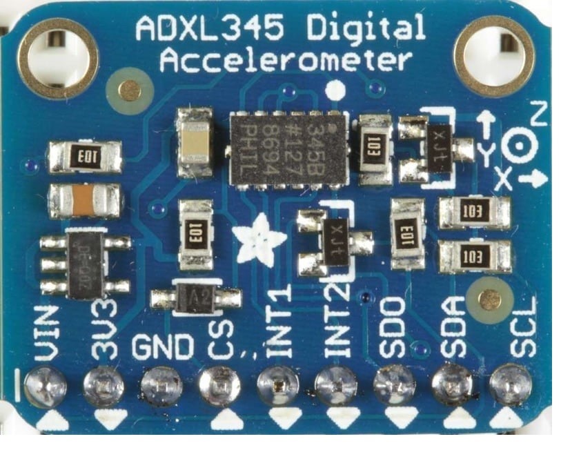
The ADXL 345 Accelerometer IC is mounted on a Adafruit circuit board. This is a basic 3 axis acceleration sensor. It has 4 sensitivity ranges from +/- 2G to +/- 16G and it supports output data rates ranging from 10Hz to 3200Hz. On the prototype board it is mounted under the BME 280. Communication with the Mega 2650 is via I2C. The Adafruit reference is at ‘https://learn.adafruit.com/adxl345-digital-accelerometer/overview’. The include is in the Library Manager under Adafruit. A sketch reference is at ‘https://github.com/adafruit/Adafruit_ADXL345’. The example sketch allows for selection of access rate and scale.
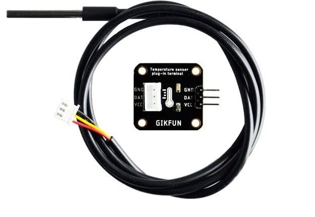
DS18B20 Waterproof Digital Temperature Sensor
The DS18B20 digital temperature sensor is based on the Dallas One-wire protocol. A reference is ‘https://www.adafruit.com/product/381’. While the sensor is good up to 125°C the cable is jacketed in PVC so we suggest keeping it under 100°C. Because they are digital, you don’t get any signal degradation even over long distances! These 1-wire digital temperature sensors are fairly precise (±0.5°C over much of the range) and can give up to 12 bits of precision from the onboard digital-to-analog converter. They work great with any microcontroller using a single digital pin, and you can even connect multiple ones to the same pin, each one has a unique 64-bit ID burned in at the factory to differentiate them. Usable with 3.0-5.0V systems. The only downside is they use the Dallas 1-Wire protocol, which is somewhat complex, and requires a bunch of code to parse out the communication.
A library reference is ‘https://github.com/milesburton/Arduino-Temperature-Control-Library’. The Library Manager has an include for the DS18B20 by Miles Burton. Installing the Dallas Temperature include also installs a OneWire.h include. GIKFUM Dat is connected to DIO 46. From the GitHub download the ‘Simple.ino’ example is used. Note that the sensor code connections are not the same across DS18B20 products. One used reversed the power/ground connection pins.
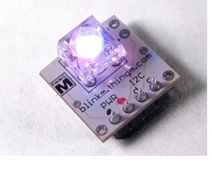
Blinkm RGB LED
Blinkm is an I2C controlled three LED (RGB) device. Each color can be controlled over a 0 – 255 range. Other options are blinking and color ramping. Blickm is a product of Thing M which has a number of other LED control products. The Library Manager has no Blinkm include. At the ‘https://thingm.com/products/blinkm’ site I found nothing that would allow Arduino control. SparkFun has a Blinkm site at ‘https://todbot.com/blog/2011/03/22/blinkm-smart-led-as-the-smallest-arduino/’ but no simple .h or .ino to load and run. Going to ‘https://github.com/todbot/BlinkM-Examples’ resulted in numbers of application programs for the Blinkm. These require loading BlinkM_funcs.h into the IDE library. At ‘https://docs.arduino.cc/software/ide-v1/tutorials/installing-libraries’ is a discussion of Arduino IDE libraries and how to load third party includes plus reference to the ‘Arduino Library Reference‘. The ‘todbot’ GitHub didn’t have a .zip to load. Another source at ‘https://github.com/darach/BlinkM’ was found which resulted in a successful ‘BlinkM_Arduino_main’ load. When applied to a sketch ‘BlinkM_Arduino_main’ shows up as ‘BlinkM.h’.
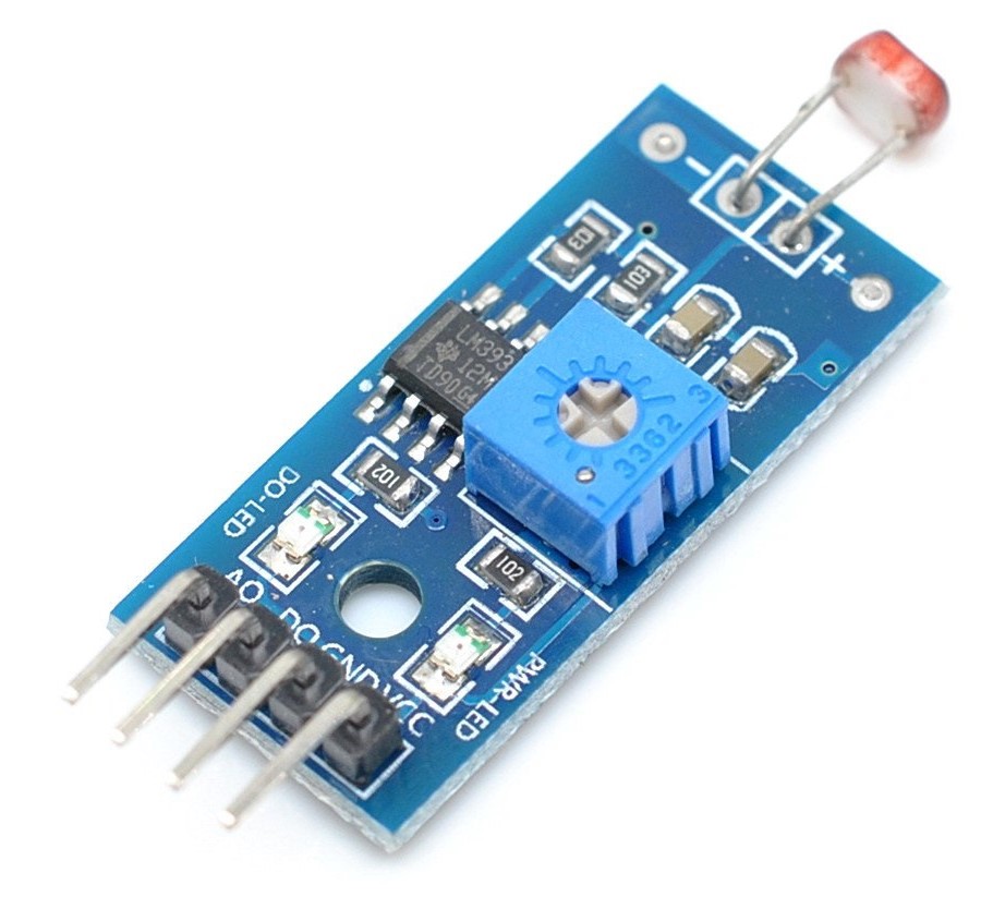
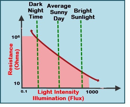
Cadmium Sulphide (CS) Light Sensor
A photoresistor (Cadmium Sulphide (CS)) light sensor is located at the left front of the Mega 2650. This is an analog sensor with a binary level detect output set by the potentiometer. The sensor is connected to A15. The level output is not connected. A photoresistor include is in the Library Manager and is installed. In ‘https://github.com/alextaujenis/RBD_LightSensor’ is a sketch for monitoring. The include is listed as ‘<RBD_LightSensor.h>’. The sketch is very simple as it just reads the analog input and multiplies to get a percentage.
Mechanical Switch
In the interest of simplicity and completeness a mechanical limit switch was added. This is connected to DIO 44.
Simple LED
An LED is controlled by DIO 43.
Composite Sketch for BME 280
The final step for this blog is to describe the software used to display the data from the BME 280, RTC, light sensor, temperature probe, mechanical switch, and accelerometer and the process of saving the data to the SD card. In addition, code was written to change the color of the BlinkM LED array and turn the on-board LED on and off. Arduino IDE 2.0.3 was used. The process was to test the code for each sensor and function and then add the device code to the overall code for the test board. It many cases some modification of the sensor and function (i.e., keypad) code was required. In the main loop code, the keypad is monitored. Pressing a keypad number selects a sensor or function for display. These are: 1/RTC hours, minutes and seconds, 2/3 axis acceleration, 3/ temperature probe, 4/ BME temperature, RH, barometric pressure, 5/ altitude from BME, 6/ light level, 7/ mechanical switch status, 8/set BlinkM LED array color and intensity, 9/ turn on board LED on/off, 0/ save sensor data and time to SD card as selected period. For RTC, accelerometer, and light level the data is shown continuously until the function is de-selected. The data is saved to the SD card in selectable periods of 10 seconds, 1 minute or 1 hour. Five hundred samples are taken. The SD save function can be ended via the keypad. Twenty entries are written to the SD card file at each time period. One of the entries is a data count. Besides the actual data, four data entries are available for other information as needed.
Data Saved and Processing in Excel
The data saved to the SD card is a sequential list. To complete the data processing, the SD card is removed and inserted in a computer (Windows in this case). The data is read in Notepad and then transferred as a column into Excel. A macro in Excel is used to parse the data into a row per period (or count). The data can then be plotted as desired. An example follows. This is for 10 second sampling. A lot can and, in application, would be done to add more plots and provide additional data description. The objective at this point is to illustrate the completion of the process.
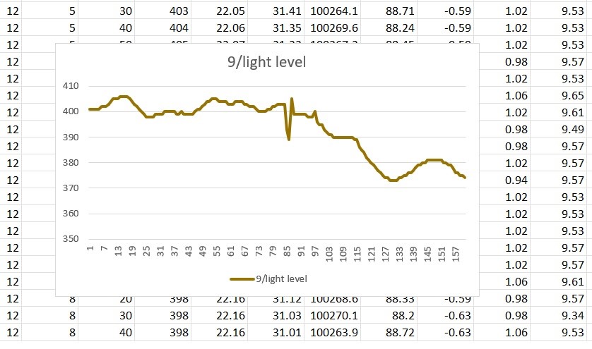
Summary of Arduino Test Board
This blog describes an Arduino2650 based instrumentation and display board which might be applicable to studying the outdoor environment. The primary sensor array of interest was the BME 280 which provides temperature, relative humidity and barometric pressure. A primary objective of the blog was to describe where information and code for the sensors and other functions of the board can be found. The data acquisition capability is of the board is described through the Excel processing and final through a plot of the light level at 10 second intervals. The test board is in a prototype form with wiring pin connected to the Arduino. An addition step for another time is to provide portable power so that the board could be taken to the field for environmental monitoring.
Next Blog
The next blog will (most likely) extend the sensors used with the Mega 2650 to include GPS, IMU and a number of light sensors.
